TCP/IP Overview - Data Link Layer - Draft
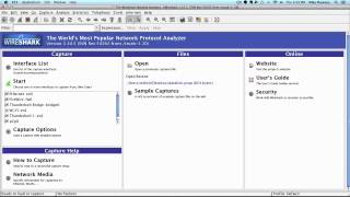
A walkthrough of Ethernet framing and packet capture using tcpdump and Wireshark. The video explains MAC addresses, EtherType versus length fields, and the difference between Ethernet II and 802.3 frames, then demonstrates live ARP requests and ICMP ping packets to show how each layer builds on the one below.
Chapters
Let's jump right in and take a look at the structure of the Ethernet header. The first thing I want to note is that you typically will not see the preamble or the FCS in your packet capture. This is because the network card will strip these away before passing the data along. Certain tools have the capabilities to show these, but special hardware is also needed to display these, so you will typically not see these in your capture. Let's go ahead and explain what the preamble and FCS are so we can move forward and focus on the fields that you will actually see displayed in the Wireshark examples later. The preamble is a signal used to synchronize transmission timing between two systems. The preamble is shown here as 8 bytes. The first 7 bytes are alternating 1s and 0s, with the last byte, known as the SFD, or Starter Frame Delimiter, ending with 2 1s. The alternating 1s and 0s allow the receiving host to synchronize with the correct pace before the actual frame begins. The 2 1s at the end of the SFD signifies that the beginning of the frame follows. Let's jump ahead to the 4-byte frame check sequence at the end of the frame. The FCS field simply holds a number that represents the data in the frame. The sending host will perform a cyclic redundancy check on the frame and store its result in the FCS field. The receiving host will perform the same check and compare its results to the FCS. If the number does not match, it is assumed that there is an issue with the frame and the frame is discarded. It's important to note that the data link layer has no mechanism to request that the data be retransmitted but the transport layer may request retransmission if TCP is used. Now that we have these out of the way, let's focus on what we'll be seeing when we look at our packet capture. The first two fields we'll see are the destination and source addresses. These fields contain the MAC address of the host that created the frame and the next hop to receive it. These addresses will change at every Layer 3 device since these devices will need to make routing decisions based on the destination IP address. Which resides in the network header. Since the data link header is stripped away to look at this information, the device will need to recreate a new header for passing it along. So just imagine that you're communicating with the server on the internet. As the frame leaves your machine, it will have a destination address of your router and a source address of your machine's network card. When the server receives this information, the destination address will be for its network card and the source address will be from the last hop before reaching the destination. Next we have the EtherType field. The EtherType field specifies what protocol header is contained in the following data field. You may sometimes see this referred to as a length field. So let's spend a moment to discuss why that is. When performing analysis, most of the Ethernet headers you'll come across will be Ethernet version 2, which is shown in this diagram. Ethernet Version 2 uses this field as an EtherType field. If you see this used as a length field, you are actually viewing an 802.3 frame. If your protocol analyzer does not specify which header type is being used, there is another method to determine this by referencing the value listed in this field. If the value is less than or equal to 1500, it is considered to be an 802.3 frame. A value of 1536 or greater is an Ethernet Version 2 frame. So just remember, if you're ever concerned what header type you're reviewing, there are a couple of different ways of determining this. Finally, we have the data field. Following directly after the EtherType field, we will see the header of the protocol specified by that field. For instance, if the value of the EtherType field is 2048 or 0x800, then the first part of the data field will be the IP header. Following the IP header would be the header used at the transport layer, the application header, then finally the payload. Let's perform a packet capture so we can get a good feel of what this actually looks like. I'm wanting to view some ARP, or Address Resolution Protocol, traffic, so I'll first need to flush my ARP cache. Doing this will ensure that when I communicate with a target machine, I will actually need to send an ARP request for that machine's MAC address. We saw in the diagram that MAC addresses are needed at the data link layer. This layer does not care about IP addresses. So to clear my ARP cache, I'm going to do arp -d for delete and -a for all. We see here that deleted 2 instances. The .1, the first one there, is going to be my default gateway. The .6 is going to be the machine I'm actually going to communicate with. So let's go ahead and do a packet capture. Let's do a tcpdump -n so it won't resolve any names or ports, -i to specify the interface, which is my case is en1. Let's write this out to datalink.pcap. Let's go ahead and only capture traffic to 10.0.0.6. Alright, since that's running now, let's go ahead and ping 10.0.0.6. Alright, so we have a few pings there. So since it only has the IP address, we flushed the ARP cache, so it no longer had that MAC address for that machine. Nobody actually went to ping that IP address. It had to send an ARP request to get that MAC address to be able to communicate with it. So now if we do an arp -a to display all— everything in the ARP cache, we'll see the .6 is in there now. So next time it goes to communicate with .6, it'll look in the ARP cache and see that MAC address in there. It will no longer have to send out an ARP request until that is expired or any other reason to delete it out of the ARP cache. So let's go ahead and go back to our tcpdump. We'll cancel out of that. So we should have all the data that we need. Let's make sure that's saved. We have the daily.pcap. So let's go ahead and go to Wireshark and open this up and take a look at the traffic. We could have easily just captured the packets with Wireshark, but it's good practice to use a command line tool instead for this purpose. Wireshark will try to load the packets into memory, so it's actually more efficient to use a tool like tcpdump to capture and filter for the traffic that you need first, and then load that capture into a protocol analyzer like Wireshark. Let's go ahead and open up the pcap. So now by taking a look at the first 2 frames in the packet list pane, we can see that my machine did indeed send an ARP request and receive an ARP reply before performing the ping. So let's take a look at frame 1 so we can actually see the data leak header we've been discussing. In the packet details pane, we can dig through the different headers and see each field displayed. If you pay attention to the packet bytes pane at the bottom, you will see the highlighted hex data of the field we are analyzing. The first line in the packet details pane gives some overall information of the frame we are analyzing. Let's take a look at the second line, which is the Ethernet version 2 header. So just like we saw in the diagram, we have the destination address, the source address, and the type field. Notice that the destination address is all Fs. This is a Layer 2 broadcast, so each machine in the same broadcast domain will receive this frame. The source address is my address. We can see that 806 in the type field signifies that an ARP header is next. If you remember from the diagram, the data field follows the type field, so the next section should be the first field in the ARP header. And it is. Notice that the only thing in the data field is the ARP header. Since ARP is only used within the same broadcast domain, there is no need for any other layer. We haven't gone over any of the fields that you see displayed in the ARP header, so let's take a look at them now. The ARP header may seem like a lot, but it simply lists what type of addresses are being used the lengths of those addresses, whether this is a request or a reply, and what the addresses actually are. The first two fields state what type of hardware address is being used and what type of protocol or Layer 3 address is being used. The next two fields specify the lengths of those addresses. The fifth field specifies whether this is an ARP request or an ARP reply. The last four fields list the source and destination's hardware and protocol addresses. Listing both of these addresses for the sender and the destination allows both hosts to update its ARP cache with the information contained. So now that we know what each field is for, let's take a look at our frame again. We see that we have a hardware address type of Ethernet and a protocol address type of IP, and the sizes of those are 6 and 4 accordingly. The opcode for an ARP request is 1, The opcode for an ARP reply is actually 2. We'll see that here in a moment. And then we have the sender and target's MAC address and IP address. If you look at the length of a MAC address, it's 6 bytes as specified by the hardware size. And the IP address is 4 bytes as specified by the protocol size. So let's take a look at the ARP reply. We'll see the opcode actually changed to 2 to specify that this is an ARP reply. And note that you'll see the sender and target MAC and IP addresses swap between the ARP request and the ARP reply. The reason that is is because the machine that's sending it will show up as the sender, and the target machine of course will show up as the target. So let's take a look at the traffic for our ping. We see that we have the same Ethernet2 header. The destination MAC address is the MAC address that corresponds to the .6 IP address that we were communicating with. The source MAC address is the MAC address of my machine that's actually sending the ICMP echo request. The type field we see here is no longer ARP. This has a value of 800, which corresponds to IP. So this means since the data field is next, the first portion of that data field should be the first field of the IP header. So we open up the IP header, the first field there follows directly after. And now we are actually into layer 3 header. Since this video is just on Data Link, we will go ahead and move to our next video and go into this packet further.
More from Jon


What No One Knows the Podcast / Vodcast featuring The Tampa Bay Wave and Jon Schipp

Meeting the Exposure Management Challenge: Key Use Cases for Success | @OfficialRapid7 #SolutionSpotlight
Spot Security Control Gaps and Non-Compliant Resources Across Your Attack Surface