Scientist Stories: Jonathan Howe, Super Resolution Microscopy
John High explains three super-resolution microscopy techniques that won the 2014 Nobel Prize: SIM, STED, and single-molecule localization microscopy. They achieve resolutions from 100 nanometers down to 10 nanometers, far beyond what conventional microscopes can see. The tradeoff is speed, photobleaching, and technical difficulty, especially for localization microscopy.
Chapters
Okay, good morning everybody and welcome back to the LMB's biophysical techniques course. We're on to the fourth talk now by John High, who's going to give us the last talk in our optical microscopy series of lectures, and he's going to go into super-resolution microscopy.
So yes, I'm going to talk to you about super-resolution microscopy, and before I do that, I think it's useful to think about the different length scales in biological imaging techniques. So depending on your sample, say if you wish to look at a whole tissue or a small mammalian organism, then you may wish to use biological imaging techniques like PET scanning or MRI or ultrasound. On the other end of the scale, if you want to look at individual molecules, then you're probably more likely to opt for electron microscopy because this has the highest resolution. But if you're in this middle, middle section here, hopefully you can see my pointer, then, then this is where you can use things like fluorescence microscopy. And fluorescence microscopy has a real benefit that there are various colors of photon, so you can do multiplexing, you can look at different targets at once. And the other advantage it has over electron microscopy is the fact that photons are not too damaging compared to electrons, so you, you have the ability to do live cell imaging. The issue with light microscopy is that the conventional light microscopy techniques like wide-field and confocal fluorescence microscopy have this hard limit which is called the optical resolution limit, which is around 200-250 nanometers, also called the diffraction limit. And if you want to get beyond that limit, you have to do another technique which is called— or one of these other techniques which are called super-resolution techniques. So these are still light microscopy techniques, but they circumvent this optical resolution limit using clever tricks. So in order to understand the reason behind this optical resolution limit, we have to think about what happens when you take an image. So when you take an image, say, of a point source of light, which could be a single fluorophore, through a lens in an imaging system with limiting apertures, the The image of that point source is not a 1-nanometer blob, it's unfortunately blurred out quite a lot because of the diffraction that occurs due to the wave nature of light. And this blurred-out blob in the image is called the point spread function, and this is what it looks like here on the right-hand side. So if we look at the XY cross-section, it forms this thing called the Airy pattern, which has a central maxima, then a minima, and then a maxima and a minima, and it forms these concentric rings which just go on and on and get dimmer and dimmer. In the XZ profile, it's, it's much taller than it is wide in the XY profile, so the Z resolution for most microscopes is worse than the XY resolution. So what you have to imagine is that in your image, every dye molecule in the, in the sample is substituted in the image with a PSF, and this influences the size of this PSF, influences your resolving power. So the, what we have to consider here, I'm sorry, is that the, there are a few criteria which are used to describe resolution, such as the Rayleigh, Abbé, and Sparrow criteria. And they define how close together, or actually the minimum distance these spots need to be apart, in order for them to be considered resolvable. And each of these criteria has an equation behind them, and the result of those equations are actually very similar, but different people use different resolution criteria, so you might see different equations out there in various presentations. Today I'm mainly going to use the Abbé resolution equation, which we'll see in the next slide. Now, sometimes when you're doing imaging, your molecules are monodisperse, so a more practical way of measuring resolution from an image is actually to look at just this central Airy disk and measure the full width at half maximum intensity, and the result of this measurement, the full width half max, is actually very close to the, to the Abbe limit, and this value for a high NA oil immersion lens comes out, generally speaking, around 200 to 250 nanometers laterally in XY, whereas the axial resolution tends to be 2 to 3 times bigger. At least this is the best case scenario for an oil immersion lens, about 500 to 700 nanometers. So where do these numbers actually come from? Well, here is the Abbé resolution limit. So it was obviously thought to be quite an important thing because they put it on his memorial in, in Jena. And you can see on the right here is the equation: d, which is the lateral resolution, equals the wavelength of light divided by 2n sin alpha. Now if we plug some numbers into this equation, we start off with wavelength. So typically the shortest wavelength that you might image with in fluorescence microscopy would be in the kind of 400 to 500 nanometer range. This term n sin alpha is the numerical aperture, it's the light-collecting ability of the lens, and you know, typically in the lab the NA is around 1, can be a bit bigger, can be a bit smaller. So you can essentially plug these numbers in and simplify this equation to lambda over 2, which gives you the value of 200 to 250 nanometers, which I've been talking about up to now. So if you want to get beyond that resolution limit, you have to use super-resolution techniques, and these three chaps were given the Nobel Prize in 2014 for their contribution to the field of super-resolution. Technologies, so I guess it must be fairly important. And super-resolution technologies can broadly be pigeonholed into one of three different classes. Sometimes techniques fall into more than one, but for today's introduction to super-res, we're just going to talk about the core techniques. So those three techniques are SIM, STED, and localization microscopy. And I will start with SIM. So SIM, or structured illumination microscopy, is a technique that aims to improve the resolution limit by illuminating the sample not with uniform light but with patterned light. And the reason why we do this is because many of the finer structures, the higher spatial frequency information, in your sample is diffracted outside the collection angle of the objective lens, and what we really want to do is push that information inside the collection angle of the lens so that we can record it and it can contribute to our final image. So as I said, to do this there's a trick that you can use, which is to illuminate the sample not with uniform light but with patterned light, and this is kind of explained in this middle section here. So On the left-hand side, pattern 1, this is our illumination pattern, and this stripy pattern is made as fine as it can possibly be, as defined by the resolving power of the lens. And then pattern 2 is meant to represent the high spatial frequency, so very fine structured details in the, in the sample, which are actually too fine to be to be ordinarily resolved, because that high spatial frequency information basically escapes the lens collection angle. But it turns out if you illuminate this very high spatial frequency sample with this patterned illumination, these two patterns interfere with one another to generate the image that you see. And then the image that you see actually contains a third pattern which is called these moiré fringes. So these moiré fringes, hopefully you can see them on this sort of diagonal here, these are a much lower spatial frequency than the information in pattern 2, and they're low enough to be captured by the angle of the lens. And what this means is essentially because we have a knowledge of the pattern's illumination and we measure this moiré pattern, we can infer what the high spatial frequency information in the sample must be. Now the issue is that each one image is just not enough, so if you illuminate the sample and you just get one image, it's stripy illumination, you haven't illuminated the whole sample, and the stripy pattern is inherently orientated in one rotational angle. So what we have to do in order to pad out the resolution in all dimensions is to take a series of images at different phases and orientations. So by phases, I mean, this is described in this image down here on the bottom left. So we take an image, we shift the pattern, we take an image, we shift the pattern, we take an image, and this phase information is important for unmixing the high and low spatial frequency information in the Fourier domain, and then you can shift the high spatial frequency information out to where it originally came from and do an inverse Fourier transform to generate an image with higher resolution. These rotations are really to ensure that you build up resolution in all directions. What we do is we plug all of these many images that we acquire all these raw, raw images, and there could be up to 25 of them if you're doing 3D imaging. And we plug them into a computer algorithm that then computes the super-resolution image. And in principle, this super-resolution image could be up to 2-fold higher resolution in X, Y, and Z, which is the reason why I've modified the resolution equation, the Abbe resolution equation here, to change the 2 to a 4. So in principle, using this method, you can get a resolution of maybe 100-230 nanometers in XY, and in Z it's still improved to maybe 250-350. So at the LMB, we're lucky enough to have a SIM microscope which is from Zeiss. It's got 4 lasers for blue, green, red, and far-red. Imaging. It's got several high NA lenses. Now the resolution is still limited by the NA, so you want to start with as high NA as possible. The camera has very small pixels, which is important for ensuring Nyquist sampling, and then we have various gratings which enable us to basically select the optimum grating for the wavelength and NA of that we're using to get as fine a possible modulation in the sample. Now realistically, in, in SIM, if you've prepared your sample very carefully, you can get up to 4-color imaging. But you should remember, if you only need to image a few colors, it's better to use shorter wavelengths than it is to use longer wavelengths. This is also true of of diffraction-limited imaging, because the numerator in that, in the Abbé equation, is wavelength. So start smaller, you get a better resolution. If you're wondering where the name ELIRA comes from, it comes from this constellation here, and it turns out at the epsilon position in the Lyra constellation, there is actually two stars, and this is used as sort of a quality control metric. So if you're if your microscope— sorry, not microscope, your telescope is performing well, then you should be able to resolve these two stars at the epsilon position. So that's where the name comes from, epsilon, E, Lyra. So here's an example of a two-color SIM image. This is a cell, an endothelial cell, that's labeled actin in blue and mitochondria in red. Hopefully you can see in the right-hand image that the resolution is improved. You can see more fine structure in the actin microfilaments, and also you can see more detail in the mitochondria. Hopefully that's coming across in the Zoom. Just to demonstrate, you can do, as I said, more than 2 colours. You can do 3 or 4 colours. These images were were given to me by Aggie, and these demonstrate the improvement in resolution and how that might be useful. So Aggie is from the Randall Lab, or was from the Randall Lab here at the LMB, and they're interested in the process of autophagy and how cells deal with intracellular pathogens like Salmonella. So in both of these images, the Salmonella are in blue, And then the other colours are various components of the autophagy machinery locating to this intracellular pathogen and targeting it for degradation. What you can see in this, in this top image, the green and the red signals overlap quite heavily, so you see a lot of yellow, whereas in the SIM image, there's a lot less yellow, and you can start to resolve these different targets from one another, and they seem to go to different microdomains. And the bottom image is just a 4-color example of this, just to demonstrate that that's possible. So the next technique I want to talk about is STED, or stimulated emission depletion microscopy. This is a point spread function engineering technology, so you actually get a super-resolution image straight off the microscope. So a STED microscope is essentially just a fancy confocal. In a confocal microscope, you have an excitation beam which is focused down to a diffraction-limited spot on the sample, and then that generates, leads to excitation, and then you get an emission spot. But instead, you have an additional laser, you have this thing called the STED beam, which is aligned on top of the excitation beam, but importantly, it's preconditioned such that at the focus it doesn't form a sort of Gaussian profile, it makes this doughnut shape. And importantly, there is a zero intensity in the middle of this doughnut. And to understand why this is beneficial, it's useful to talk about the stimulated emission process. So if we look at this electronic state diagram in the bottom left, This shows you the normal excitation and fluorescence regime. So if you absorb a photon, you go from the ground state to the excited state, there's some internal conversion, and then a photon is emitted. And the exact jump energy, the exact energy difference between the excited and ground state bands that that defines the exact wavelength of the emitted photon, which is the reason why we have a spectrum. Now, it turns out that when a molecule is in the excited state, if it's bombarded with, with a high intensity of photons which match one of these energy gaps, then the molecule can actually be stimulated to emit a photon of the same wavelength, and that process is called stimulated emission, and it's what the S and the E in laser STAN stands for. So how do we practically use this? Well, we, what we do is we, um, we pick a wavelength for the STED laser beam which sits at the far end of the emission spectrum of your fluorophore, and then what that means is all the molecules around the outside of the excitation spot are induced to undergo this stimulated emission process, which means that only those molecules in the very center are able to undergo the regular fluorescence process, and therefore that means the effective emission spot is made much smaller. And because your emission PSF is much smaller, your resolution is better. The nice thing about STED microscopy is that in theory you have limitless resolution, so your resolution is defined by how high your, your STED laser power is. So on the left-hand graph here, you can see resolution on the y-axis and STED power, or I, on the x-axis. And the higher you turn the STED power, the smaller the emitting volume becomes, the better the resolution is. Now, Each molecule, each fluorophore, has a property called the saturation intensity, which is the STED power which is needed to quench emission by 50%. And if we take this saturation intensity term and also the STED power I, and we plug them into a modified version of Abbé's equation, we get this. And you can see from this modified equation that Essentially, the lower the saturation intensity, or the higher the STED power, the smaller this term d becomes, smaller the emitting spot becomes, and the better the resolution can be. And typically we can get resolutions of 25 to 80 nanometers for biological samples. But importantly, if you're squeezing the PSF only in X and Y, your Z resolution doesn't get any better, so your Z resolution is the same the same as confocal. But there is a way of improving resolution, which I'll come on to in a second. So one thing to remember is that the STED microscope is basically a confocal, so it's raster scanning this, this excitation and superimposed STED spot over the sample. And what this means is that any given molecule in your sample is exposed to multiple rounds of excitation and STED depletion before the imaging spot is this green spot actually reaches it. So this can lead to quite a lot of bleaching, so it's very important with STED that you make your sample very carefully, use anti-fade agents, get the labeling density as high as you can. Now I mentioned a minute ago that we can improve the z-resolution as well. Now one method of doing this is to is to separate the, the STED laser into two paths. In one path, you precondition the STED laser beam so that it forms this donut shape in XY, and in the other path, you pre-shape it so that it forms these axially shifted intensity lobes above and below the plane of focus. Which are represented here. So what that acts to do is squeeze the emission volume down in z. So what this enables us to do is actually tune the amount of light we send down each of these two paths such that we squeeze the emitting volume in x, y, and z, and we can even achieve an isotropic resolution of say 125 nanometers or so. So we're lucky that we have one of these STED microscopes at the LMB. It is essentially a modified version of the SP8 confocal from Leica, and the modification is that it has some extra components, and they are represented in this image. Basically everything to the left where I'm pointing now, everything to the left of the scan head are the STED components. So we have a tunable white light laser for excitation. It's pulsed as well, which is beneficial because it means we can use that to improve resolution slightly. There are several STED lasers, um, which are very high power because that's necessary. One at 592 for depleting green dyes, one at 660 for depleting red dyes, and one at 775 for depleting far-red dyes. There's this STED alignment unit which is bolted directly onto the scan head, which is the thing which basically ensures that the STED donut is aligned on top of the excitation spot. And some of the detectors also have time-gated electronics which enable, enables us to improve the resolution slightly in combination with the pulsed excitation source. One thing to remember is, just like with a regular confocal, the the scan time scales with the frame size. However, instead, because we're hoping to achieve higher resolution, you need small, even smaller pixels than you would in regular diffraction-limited confocal imaging. And this is to ensure that you have Nyquist sampling. And in theory, if you're going to achieve, say, 40 nanometer resolution, then your pixels need to be around 20 nanometers big, which is like 4 times smaller in X and Y than you would typically use in a confocal, which means that your scan time, if you keep the same pixel dwell time, is going to be 16-fold slower. We do also have a resonant scanner on this system, so if the intensity of the fluorophore is bright enough, then you can use this resonant scanner to improve scan speed somewhat. So just to show you some data, these are some HeLa cells that I labeled with an anti-alpha tubulin antibody. And hopefully you can see the STED image in the middle, which is in red here, is higher resolution than the confocal image on the left. And if we blow up the merge, it's even more clear. And if we take a line profile across these microtubules here, you can basically show in a graph, although it's obvious, that what looked like two kind of fat microtubules actually consisted of a bundle of two and three, so five in total. And this was only really resolvable when we did the STED imaging. One useful thing to do when performing any microscopy is to try and estimate your your resolution is to calculate the full width half max, as we described earlier. So if we, if we take a single microtubule and draw a line profile perpendicular to the direction of the microtubule, then we can estimate the resolution. So if we do this on this microtubule down here, for the confocal we get a value of 250 nanometers, which is to be expected for this wavelength of right, whereas in the STED it's down at 90 nanometers. But I did say to you that, you know, you can achieve better resolution than this. So the answer is, why am I measuring a resolution that's only 90 nanometers when actually the diameter of a microtubule is 25 nanometers? And I will come on to explain that at the very end of the talk. Just to give you another example, these are primary rat hippocampal neurons. This is an image just given to me by Jake Watson, formerly of the Greger lab, and it's difficult to see until I blow it up, but you can see here that basically what's labeled here is two molecules of the postsynapse. One is the GluA1R, or GluA1 receptor, that's in green, and the second thing is a molecule a sort of structural molecule called PSD95. And these two components are both in the postsynapse, and you can see in the confocal image that they appear to overlap quite heavily, which would make sense because they're located to the same side of the synapse. However, when you do STED, you suddenly find that all of that, or a lot of that, colocalization falls away. When our resolution improves. And what you can see is actually the GluA1 receptor is decorating around the PSD95. Here's another example, so the same type of sample, but the labelling is slightly different. So we have PSD95 again, but this time it's green, and then in red we have a presynaptic marker called Bassoon. So essentially what we're looking here is down the synaptic cleft, and you can see in the confocal image that these two sides of the synapse are just about resolvable, although there is some yellow in the middle here. Whereas in the STED image, you can start to see these small clusters, and there's basically no yellow because we're able to resolve the pre- and the post-synapse. Now just to demonstrate to you that we can do 3 colours, here's an example from Sophie, formerly of the Siemen lab in the CIMR. I don't know precisely what the staining is here, but I know they are membrane receptors being trafficked through recycling endosomes, and what you can see in the confocal image is that we have quite a lot of colocalization. So we have yellow and we have cyan, which is reflective of various molecules being perceived to be at the same location. But then when we do the STED imaging, we get much more resolution. Unfortunately, I don't have a further blow-up here, but essentially you can see, for example, in this green thing here, this green blob becomes a circle, so that's probably something like a vesicle. And a lot of the colocalization has gone away. We can see the individual colors more clearly separated from each other. Okay, so the final type of SuperRes technique that I'm going to talk about today I'm going to talk about today is called localization microscopy, sometimes called single molecule localization microscopy. And localization microscopy actually comprises many, many techniques, all with their own acronyms. It's quite confusing. But the techniques, the original techniques that came underneath this umbrella term were PALM and STORM. Later techniques are sort of derivatives of that, so I'm going to talk about PALM and STORM mainly today. So localization microscopy works like this: in the standard diffraction-limited image, you have multiple fluorophores, and the PSFs of those fluorophores essentially overlap, so they're unresolvable. So you can't really tell in this blob how many the fluorophores there are. So in order to get around this problem, what we do in localization microscopy is image these molecules separated in time. So we somehow contrive to have only a subset of molecules switched on in any frame of a time series which we collect. And what this enables us to do is localize the centroid position of the molecules, and then we build up a map of these centroid positions, and this is the super-resolution image. And in this technique, you can achieve resolutions of, say, even 10 nanometers at best, but typically 25 to 40, and the z-resolution can also be improved down to 50 nanometers. The question is, how small can we make these, these blobs in the super-res sort of map that we generate. And that's defined by this equation here. This is the localization precision equation that most people follow from Thompson and Webb, and this contains various terms including— these are basically uncertainty or noise terms. And we start here on the left with the photon noise, in the middle we have the effect of pixelation, and on the right we have the effect of the fluorescent background. Now, if you design your microscope appropriately so that the pixel size is not limiting, and if you design your sample such that the background is not too high, then effectively these latter two terms become negligibly small, and then what you're left with is this first term, and we can simplify the equation then to localization position is approximately equal to the width of the focus spot divided by the square root of the number of photons collected. Now this is sort of explained in this, in this picture here on the bottom right corner, and it's logical, right? If you've got more photons, then you can see better the focus spot, or the PSF, and therefore you can more accurately localize the molecule within the PSF which has given rise to that fluorescence signal. And this is actually simulated data, both on the right and the left. You can see from this plot on the left that essentially the lower the background, or the more photons you collect, the better the localization precision. So in practice, what happens is you take many, many images. You take a time series of tens or even 100,000 images on a camera, maybe a CCD camera. And then for each time point, what you need to do is locate— so find the spots and then fit those spots to find their centroid position. And then what you do is place an assignment in the, in the super-res image at that centroid position, and you give a— normally what people do is they give a Gaussian profile to that spot, the width of which is proportional to the localization precision. So very well-localized molecules where lots of photons were detected are represented by a bright, narrow spot in in the super-res image, whereas very poorly localized molecules where there are very few photons are very broad blurred-out spots, they don't contribute as much, which seems fair. Now I mentioned that there are various different types of localization microscopy technique, and the first one I'm going to talk about is Photoactivation Localization Microscopy, or PALM. Now PALM uses optical highlighter fluorescent proteins, which were introduced by Ben in his talk on Tuesday. These, um, there are various types of optical highlighter fluorescent proteins, but the most useful ones for PALM are the photoactivatable fluorescent proteins and the photoconvertible fluorescent proteins. And the way in which they work, the way in which you use them for PALM, is ever so slightly different. So if we start with the photoactivatable fluorescent proteins, what you essentially do here is, is express in your cells, you know, by transfection, or make a stable cell line which express your protein of interest genetically fused with this fluorescent protein, such as PHEFP, or PAM cherries. They come in different colors. So when you look down the microscope, say, PAGFP in the green channel, initially you see nothing because all of the GFP, or hopefully all of the photoactivatable GFP molecules, are in the dark state. But then what you do is you, you take a time series image where, and time series where you slowly trickle in light at 405 nanometers, UV light, and this UV light actually induces a conformational shift in the PAGFP chromophore, which turns it into the green fluorescent version. And the idea here is that we just wish to switch on a very small subset of the molecules in the field of view in any frame, and then we image them, get as many photons as we can out of them within the integration time of the camera, and then hopefully they bleach, and then in the next frame maybe another PAGFP molecule will become activated and then can be imaged and localized. And we just repeat this process for many thousands of frames. The photoconvertible fluorescent proteins are probably easier to work with. They start off one color, and then when you hit them with a certain wavelength of light, often UV, you convert them to a different color. So the example in this diagram at the bottom is something like EOS. So it starts off green, so if you're imaging in the red channel initially you would see nothing, but then as you start to trickle in a bit of 405 illumination, you start to convert the molecules from their green to their red form, and then you get as many photons as you can from those converted molecules in each frame, and bleach them, and then with each frame a new subset of molecules will come on. Obviously the main benefit of the photoconvertible over the photoactivatable fluorescent proteins is the fact that you can see them to begin with, so you can tell which of your cells are transfected. But the downside is they take up more than one channel, so they're not as easy to multiplex with. Okay, so that's PALM. That uses, as I said, fluorescent proteins. Another type of localization microscopy technique is called STORM, stochastic optical reconstruction microscopy. STORM doesn't use fluorescent proteins, it uses regular organic dyes which are commercially available, such as Alexa488, Ato647, and these obviously you can buy them as fluorescent tag-to-secondary antibodies. So it turns out that a lot of these organic dyes undergo a photo-switching process in the presence of millimolar concentrations of reducing thiols like beta-mercaptoethanol, and therefore if you bathe your sample in such a solution, then you can induce this photo switching to occur. And if you can get the conditions just right, you can make it such that the majority of the molecules are in the off state, and only a few of them in any frame are in the on state. So this is kind of demonstrated here in this, in this electronic state diagram in the bottom left corner. So what you have to imagine is ordinarily when you image by fluorescence microscopy, the molecules go from the ground state to the excited state with the absorption of a photon, and then they emit another photon, and they cycle through this process many, many, many times. And the fact is, each time they do this, there is, there is a possibility that they might return to the ground state via this triplet state, which is slightly longer-lived. And from this triplet state, they can be reduced to this long-lived off-state. And this is essentially what we aim to do in a STORM experiment. So in this, what we do is we illuminate the sample with very high-intensity excitation power to get the site, get the molecules cycling through this, um, through this, um, absorption and emission process. And then hopefully at some point they end up in the triplet state and are then reduced. And because they live for a long time in the off state, you sort of start to shelve molecules in that off state, and you aim to get 99% of the molecules, if not more, in that off state. So only a few of the molecules are emitting at any one time. Now from this off-state, the molecules obviously need to get back to the fluorescent state in some way, and this is an oxidation process, and this can actually be facilitated quite often using UV light, so it's a kind of a photooxidation. So I've got a movie here which is an image, a movie that I took of Alexa647 stuck on glass,. And what you can see in this movie is that when I move to a new field of view, all the molecules are switched on. And then as I illuminate with high-intensity Alexa 647 laser power, the molecules start to switch off. So you see there, they're getting switched off, most of them are being shelved, and then If the blinking becomes too sparse, I can add in 405-nanometer light, which is what I'm doing here in bursts, and that induces this oxidation process and enables me to regulate the blinking density so that I'm not taking all day to take a single image, because you need many millions of localizations normally on a typical biological sample. So I should warn you that some of the dyes that we that are the brightest dyes are also far more easily oxidized, and therefore, in order to shelve enough molecules in the off-state, you have to use oxygen scavenging systems such as glucose oxidase and catalase. But this is just another component of the so-called blinking buffer, and actually, there's been quite a lot of development in blinking buffers in recent years. So now there are storm buffers that work for many, many different fluorophores simultaneously, so that's very helpful. We have a STORM microscope which we purchased from Nikon, it's shown here. So this, this microscope has a turf illuminator which is helpful for improving the background level, which as we spoke about a few slides ago improves our localization precision. It has 4 lasers, so we can do blue, green, red, far-red imaging. High NA objectives, which is a useful starting point. Very sensitive camera. And what's actually particularly useful in this system is it has a thing called Perfect Focus System, PFS. This is a hardware focus stabilization, and it basically is really, really helpful when you acquire STORM or PALM data, because the acquisition time can actually be, you know, many tens of minutes, and you really don't want the sample to drift in Z at all during that time, otherwise the image that you generate will basically be a Z projection image. So the PFS basically eradicates z-drift. And then we also have a software XY drift correction, which basically deals with that lateral movement that might happen over the course of the hour or so of imaging. There's also this cylindrical lens which you can't quite see in the image, but it sits between the microscope body and the camera, and this enables us to give some 3D, so z-position mapping of each of our molecules, which I'll show you in a moment. So I mentioned TIRF microscopy. So TIRF is a very useful illumination technique when you're doing single molecule imaging because it restricts excitation to very close to the COVID glass, so the whole sample does not get illuminated. The way it works is you basically direct the laser at the sample not straight at the lens but at the edge of the lens, and then it approaches the sample at an angle, and if the angle exceeds this so-called critical angle, then the phenomena of total internal reflection occurs, rather than the light passing through the COVID glass and, and being refracted. So at the surface where the total internal reflection occurs, this evanescent wave is generated, and this decays very rapidly in z. So this means that excitation can only occur if the fluorophores are really close to the COVID glass, and we're talking about a couple of hundred nanometers at most. So this is only applicable if you're, if you're working with, say, cell surface membrane molecules like receptors, or maybe you, you do some sort of in vitro reconstitution experiments like you might microtubule molecular motor movement. Okay, so the reason I'm introducing this is because this next image is a TIRF image, so I felt I should at least explain why the background is so low. This is an image of HeLa cells labeled for Cavin1, which is a caveoli coat protein, and the secondary antibody I used here is Alexa647. So this is the TIRF image, And then on the right is the storm image. Hopefully you can see over Zoom that the dots here in the storm image are much, much smaller. And what I can actually do is blow up this image over and over again until we can see individual capillae, and they're not blobs any longer, they're sort of cup shapes or maybe even full enclosed internalized vesicles. So this tells us that the resolution must be, you know, at least sort of 50 nanometers. So yeah, this is clearly a very powerful technique. Just to give you another example, microscopists, super-res microscopists, always like to show microtubules. So here's an example of microtubules. This, this now is not TIRF because the microtubules are up higher in the cell, So they're not necessarily in the turf plane. So this is a regular wide-field image, and then the right example is the STORM image. And if we blow that up, hopefully you can see that the level of resolution is much higher in the STORM image. And if we use that trick of taking a line profile across an individual microtubule, we can estimate the resolution. And in the, in the wide-field image, it's around 350 nanometers, which is to be expected for this long wavelength dye. But then in the, in the STORM image, it's down at 70 nanometer resolution, so even better than on the STED. This is still not at the resolution— well, this is still not at the diameter of the microtubules, which I'll explain in a moment, even though our localization precision for each individual fluorophore is probably 10 nanometers. So as I mentioned, we have this cylindrical lens which enables us to give a z-position to every localized molecule. So the cylindrical lens deforms the point spread function in a manner dependent upon its z-position. So at the focal plane, it's a nice symmetrical blob. If it's above the focal plane, it's elongated in x, and if it's below below the focal plane, it's elongated in the y-axis. So what this enables us to do is to go from this STORM image, which I've already showed you, to this depth color-coded image like this, which is basically an extra dimension of information. Just to demonstrate that we can do multicolor STORM, here's an image from Kalina, formerly from the MRC Cancer Unit. She was interested in homologous recombination upon radiation-induced damage, and she was looking at these two molecules. I'm not even sure precisely what, what their roles are, but you can clearly see that the magenta and the green molecules overlap heavily in the wide-field image, whereas in the STORM image they're very well resolved. So, just to come back to this microtubule thing, I've told you that photon number is very important because it limits the precision of single molecule localization, but also signal-to-noise in all super-resolution techniques. But photon number is not the only thing that defines the resolution, it also depends on the labeling density, and this is This is explained by this smiley face in the bottom left corner. So if you imagine this smiley face is our structure of interest, and we label it somehow, maybe with fluorescent protein or with, with antibody, if our labeling density is not very high, you can't even make out the structure. So it doesn't matter if your individual molecule localization precision is 10 nanometers, if you've got so few dye molecules on the structure, then you can't tell what it is anyway, so your image resolution is actually quite poor. But the more and more dye molecules you can somehow attach to the structure of interest, the better and better we can observe that in the image. Now, when you start to get very high resolution, which you can get in STED and also in Storm, you run into issues of label size influencing your achievable resolution, and this is most severely affected when you use indirect immunolabelling. So this is an IgG, which is about 10 nanometres tall. So if you imagine you use the primary and a secondary IgG, then your structure of interest would be, um, would, you know, your fluorophore itself could be up to 20 nanometers away from the surface of your structure of interest. So in the case of the microtubule, which is this red, this red bar here, if you've got primary and secondary antibodies stuck onto this microtubule, it goes from being a 25 nanometer diameter structure to a 65 nanometer structure, and this is the thing that we can actually observe. So what this tells us is that ideally we want to use smaller probes than IgG. So the obvious candidate would be to use a fluorescent protein, but the issue with fluorescent proteins is they may be small, they're like 3 nanometers or so in diameter, but they generally output about 1/10 of the number of photons as an organic dye, which means your localization precision then takes a hit. So a better option would be something like a nanobody, and you can get nanobodies, which are these really tiny antibodies. You can get nanobodies against things like GFP, so you can express your protein as a fusion, fused with GFP, which is quite small, and then detect it with this tiny nanobody, which itself is labeled with an organic dye. And then that enables you to basically minimize the total size of, physical size of the label, and achieve the, maybe achieve the resolution of the microscope. So just to compare the methods, to conclude, obviously, you know, I've only talked about the core super-res methods here, and there are many sort of variants of those now. But in principle, the one which gives you the highest resolution is localization microscopy. But unfortunately, because of the way in which it works, you need to take many tens of thousands of images to build up one super-res image, so it's inherently quite slow. Slow, so the temporal resolution is very, very poor. If you want to go faster and you don't really need that big an improvement in resolution, then SIM is actually quite an attractive option. Because although you have to take, you know, up to 25 images or so per Z-plane, if your exposure time is relatively short, a few hundred a few hundred milliseconds, then you can acquire an image every few seconds. So this is probably one of the most live cell compatible super-res techniques. STED sort of sits in the middle, so its resolution is better than SIM but generally not as good as localization microscopy. Its temporal resolution is quite variable, and it really depends on the the area you wish to scan. As I mentioned, the frame size depends on the field you're scanning, so if you illuminate, if you're interested in just a very small sub-area of the cell, you can zoom in a long way, make your scan area very small, and maybe acquire multiple frames per second. So if we think about multiplexing, so this is how many colors you can do. SIM again is the most flexible. Stead, you're limited by the number of stead laser lines you have. Essentially you have one stead laser line per emission color. There are tricks you can do to expand that, but generally speaking, people don't make use of those tricks. Localization microscopy on on the other hand, is arguably the most restrictive, because you need to find, either introduce enough optical halides or fluorescent proteins into your sample, or find a blinking buffer that works and achieves the necessary density of blinking events for multiple fluorophores. So it's not a trivial exercise. In terms of post-processing, STED, as I mentioned, is the only is the only technique that outputs a raw super-res image. You can deconvolve that if you wish using a STED point spread function. SIM and localization microscopy each require more post-processing, so in both of them you have to be careful about artifacts. And at the bottom here I've got just a few tips if you're thinking about starting to do super-res imaging. So the first one is always to use a number 1.5x 1.5 cover glass, ideally the sort of low tolerance or high precision versions, because the lenses are designed to work with a number 1.5 cover glass. You should try not to deviate from that too much. If possible, use phenol red-free media. You don't really need phenol red in there to check the health of your cells. You can always look down the microscope in TC to see if they're happy or infected. Removing the phenol red will just improve the background level. One other important thing is the matching of the refractive index of the immersion media, which is normally oil for a high NA lens, with that of the sample embedding media. So using a higher refractive index mounting media like ProLong Diamond or ProLong Gold TDE is beneficial for that reason. It basically reduces this spherical aberration, which degrades the shape of the PSF. And also one benefit of these, the commercial antifade agents, is that they come with— sorry, one benefit of the commercial mounting media is that they come with antifade agents, which can improve the longevity of the sample. Finally, at the bottom here, if you're considering immunostaining, it's a a good idea to increase antibody concentrations to ensure the labelling density is as high as it can be. Obviously, if you're using more antibody during the labelling steps, it's wise to also increase the number and duration of the wash steps following the antibody incubation. But this can really have a big effect on your achievable resolution. Okay, so with that, I've got some acknowledgements up here. And you're welcome to read those, and I'm happy to take any questions via the chat, I think. So if anyone's got any, feel free to post them. At the moment there's none.
Yeah, if people could use the Q&A box. Well, that was a great talk, John. It's all very, very well explained, so maybe perhaps you've We've covered everybody's questions already.
Well, apparently so.
So in terms of— I've got a question. I mean, so in terms of a user actually using these different techniques, then what's the most tricky or difficult technique to kind of get to be trained in or actually use in practice?
I would say that localization microscopy sort of scales with the achievable resolution. So SIM is not that much different to using a regular wide-field microscope, and STORM, STED, you know, you have to take great care in how you prepare the sample, and there's more parameters in the software that you can adjust, but normally people don't have too much problem. STORM or localization microscopy just requires particular dyes, it requires you to be able to make the linking buffer, and that linking buffer needs to be suitable to get the same density of linking events, or an appropriate density of linking events, for all of your different dyes. And then then you've got a lot of basically flexibility in the analysis side of things. So you have a lot of control and input that you have to give over what is classed as a true blinking event. So yeah, there's just a lot more to do on the sort of image or storm reconstruction side of things. Great. I see I've got a question. Read it. So what's the maximum field of view of each technique? Well, essentially it's the same as in regular wide-field imaging. There's, you know, you can use, generally speaking, you use higher NA lenses just to achieve better resolution, because if you start at a high NA, which normally means high magnification, you can normally get a bit further. So, you know, you can fit a whole cell in the field of view, a whole mammalian cell, several tens of microns. But yeah, really it depends on exactly what it is you want to do. If you want to do live cell imaging by STED, then your maximum field of view will be much the smaller, because you're going to need to zoom in quite a lot and reduce the scan field. Thanks for asking a question though.
All right, any other final questions then? No? Okay, great, great, John, that's fantastic. So thanks for giving this talk, and thanks for everybody turning up today, and you can join us again next Tuesday when it'll actually be me giving a talk on, on fluorescence spectroscopy. So we're going up a scale into solution-based methods, and join us then. Thanks very much.
More from Joshua





Scientist Stories: Hans Waterham, The value of phenotypic assays in peroxisomal disorders



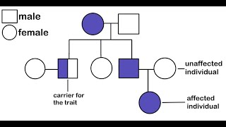
Scientist Stories: Joel Zlotogora, Genetic carrier screening programs for reproductive purposes