How To Optimize Section Control | John Deere Generation 4 Display
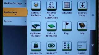
Learn how to set up section control on a John Deere Generation 4 display to reduce overlap and waste in seeding and spraying. The video walks through machine measurements, mechanical delay settings, and the LookAhead feature to optimize your operations.
Hello. Today I'm going to talk to you about Section Control Optimization. This video is created with 21 software on the Generation 4 display, so some features and functionality may differ if comparing to a different version. This material does not replace the operator's manual but is supplemental material. Only read operators manual prior to machine operation for more information. The Help center content on a Generation 4 display is also helpful for additional setup details for specific machines. This is an example of a simple setup scenario on a self propelled sprayer. These values are measured on the machine with a tape measure to confirm accurate input values. Some machines will pre populate many of these dimensions, but it is always best practice to confirm that they are accurate for your specific machine. Next, let's look at a more complex example of a multi bin air cart and cedar with a tractor and implement. We require additional offset measurements to accurately model the machine dimensions. Again, many of these dimensions may be pre populated, but we do recommend confirming the accuracy of your specific machine and implement prior to use. Refer to the Generation 4 Display Help center for additional pictures and guidance when setting up machine dimensions. With the required dimensions entered the the system is now able to model specific locations of the control points relative to the GPS receiver position. Mechanical delay settings are intended to account for the electrical and mechanical system delay.
Mechanical delay on time should be measured.
From the time that it takes to.
Manually turn on seeder product flow to the time when the seeder product is being applied to the crop canopy or ground at the desired rate.
Mechanical delay off time should be measured from the time that it takes to manually turn off the seeder product flow to the time when the seeder product stops being applied to the crop canopy or ground. These measured values are entered into the display in the machine or implement profile. Note that for some implements such as multi bin air carts, the individual tanks can be measured to account for different lengths of seed or product travel time from each bin to the ground. Keep in mind, mechanical delay on off settings are intended to be a precise setting and can be further calibrated using performance tuning. Mechanical delay times should not be modified to adjust the system's placement of seed or product to the operator's preference. To make these adjustments, an operator should use overlap settings which we will discuss later in this video. Performance tuning is used to precisely dial in the machine's or implement's mechanical delay times. This calibration tool uses two operator inputs measured during a test run to automatically calculate and adjust mechanical delay times. To make these adjustments, the system requires the length of a skip or overlap witnessed on the ground and the machine ground speed used during that test run. Ensure that the GPS accuracy reading is good. Verify that all previously discussed dimension setup is complete. If using an implement receiver, ensure that it is set up with the correct offsets prior to performance tuning. To begin performance tuning, plant a headland pass, then plant a pass perpendicular to it. Make sure to maintain a constant speed when entering and exiting previous coverage. Make note of the ground speed when entering and exiting previous coverage as performance tuning will ask for this speed. Dig for seed in multiple rows and measure the average length of skip or overlap from the last seed to the first seeds in the headland row. In performance tuning on display, select skip or overlap as needed. Enter the length measured in step two and then enter the previously noted machine ground speed. Select your desired seat placement setting. Select ok. Mechanical delay time is automatically adjusted to correct for the skip or overlap. If needed, run additional paths to verify tuning adjustments consistently. Place seed in the correct location now. Overlap settings can be adjusted if desired to adjust seed placement, for example if the operator desires additional overlap to ensure that no undesired gaps exist in coverage. Overlap settings allow an operator to customize the amount of skip or overlap that the system will apply laterally based on their preferences for the operation. This setting impact is not seen if headland approach angle is perpendicular. Unless an operator select 100% plus additional overlap on all configurations except the row crop planter section control will always command based on the edge of the previous coverage.
Overlap settings for row crop planters are designed to allow additional fine tuning of the seed placement in addition to percent overlap. Operators can also define if they want the seed to be planted right up to the center of the first headland row, or they can customize a specific amount of intentional skip or overlap as desired. The seed placement setting allows you to set a specific inline offset for the sections to achieve intentional skip or overlap relative to the first headland row. The effect of plant to row is essentially to add half of a row width of overlap after the edge of previous coverage is crossed.
If intentional skip is set to half.
Row width, then a row crop planter's overlap settings will behave the same as other machine types. Let's view some examples of overlap setting adjustments. In this first example, we start off with the system default setting of previous coverage overlap set to 50% with the seed placement setting of plant to row. In this example we are using a row crop planter with two row units per section. Let's say that this operator prefers to see less of a gap between the near parallel passes on the left side of the screen. This gap is expected in this area with the overlap percent at 50% but can be tuned out if an operator would rather have overlap into the near parallel pass to adjust for this gap. One option would be for the operator to adjust the previous coverage overlap setting to 100%. In this scenario we have also left the seed placement setting at plant to row. Note the additional overlap that is seen on the angled approach passes on the right hand side of the screen and the overlap that is now seen between the near parallel passes on the left side of the screen. In this scenario the operator has decided that this is more overlap than is desired and they also decided that they would like to apply seed only to the edge of previous coverage to and not to the center of the headland row. If an operator prefer to plant up to the edge of the previous coverage instead of planting right up to the center of the row, they can configure an intentional skip of half their row width. By doing this and leaving the overlap setting at 100%, this operator has achieved their desired result. Note that the impact seen at the non perpendicular passes on the left and right side of the screen when making adjustments will be less with one row unit per section and will be more significant with a higher number of row units per section. Unlike dimensions and mechanical delay settings which are real measurable values, overlap settings should be set and adjusted as needed to meet the operator's desired amount of skip or overlap for the specific operation being performed.
Now that we have successfully provided the.
System with our machine and implement dimensions, we have accurately tuned our mechanical delay on and off times and defined our desired overlap settings. We can use this information along with the machine speed to calculate a look ahead for section control points. This lookahead provides the system with the location that an on or off command must be sent at the current speed and heading in order to accurately start or stop product flow in the current control location.
Here you can see the look ahead.
Visualized on the map as the orange bar in front of the green work point.
The following clip will show how to enable and use the LookAhead feature.
The first pass will demonstrate good operating.
Behaviors that will not cause degraded performance.
And the second pass exhibits operational behaviors that can cause common performance complaints.
Maintain constant speed and heading between when.
The look ahead line begins crossing transition area and work point finishes crossing it. Section commanded on is orange, section commanded off is white.
SA.
Poor performance resulting from acceleration after section control command is sent and before workpoint crosses transition. Poor performance resulting from deceleration after section control command is sent and before work point crosses transition, Poor performance resulting from acceleration. After a section control command is sent and before workpoint crosses transition.
Poor performance.
Resulting from heading changed. After Section Control command is sent and before workpoint crosses transition.
More from Francisco



Desh Ke Superhero | Mr. Madhava Rao | Faster Pole Installation with GreenSystem™ Post Hole Digger


En CasaToro John Deere encuentras el respaldo que necesitas para mantener tu maquinaria lista