This is a YouTube video titled "John Deere Combine GoHarvest: Concave installation on MY15 S Combine equipped with ACI" created in January 2018. The content is an instructional video detailing the step-by-step procedures for removal, installation, leveling, and calibration of threshing concaves on a John Deere S series combine harvester, focusing on safety and mechanical adjustments for optimal performance.
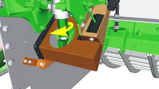
Performance, productivity and exceptional harvest experience. Go Harvest. Get the most out of your S series combine today. Always follow safety instructions and understand all safety decals according to the operator's manual. Always use seat belts when operating the machine or riding as an observer. When parking and leaving the machine, disengage the header and separator. Move the multi function lever to neutral and apply the parking brake. Shut off the machine, remove the key and lock the cab. When performing service operations where the engine must be started, make sure everyone around is aware and are clear of the machine. Enter the cab, sound the horn and start the engine. This video will demonstrate procedures for removal and installation of threshing concaves. In addition, the following concave leveling and calibration procedures will also be detailed. Start the engine and press the threshing clearance button and set the threshing clearance to 5. This will allow easier access to remove the Z bar hardware. In some machine configurations, threshing clearance may need to be set higher for access. Set the parking brake, shut off the engine and remove the key. Shift the rotor gearcase selector handle to the neutral position. Remove shielding and separator inspection covers on the left side of the machine. Remove one separator grate section or two heavy duty grate fingers to allow access to turn the rotor. Be sure the left side auger bed divider is in the lowest position in the trough. Remove the concave leveling cap screws from the storage position on the Z bar and install them through the rail to hold the concave and Z bar assembly hand. Tighten the lower nut against the Z bar bracket and slightly tighten the upper nut against the rail. Leave space between the lower nut and rail to allow clearance for zeroing adjustments. Remove the base of the rubber seal on both cylinders and lift upward. Remove the pin and safety stop from both cylinders. Loosen the cylinder stop jam nut. Turn the stop on both cylinder rods, lowering the stop at least 15 millimeters from the original position. Remove the quick locks and pins from both cylinder rods. Remove shielding as needed to access and remove the separator inspection covers on the right side of the machine. Remove the spring pin from the concave retainer. Lift the concave retainer and remove the handle from each concave section. Return to the left side of the machine and loosen the cap screws between the Z bar and concave sections. Use the leveling cap screws to adjust the Z bar and concaves up approximately 10 millimeters until the middle concave can be easily removed. In some machine configurations where a tall rice dense pack is installed The Z bar may need to be removed. If removing the Z bar, remove nuts and linkage arms between the Z bar and position sensors. Turn the rotor so a gap in the threshing element pattern is at mid concave. Be prepared to lower the heavy concave sections with either an additional person or pry bars capable of supporting and slowly lowering the sections. Remove the cap screws between the Z bar and concave sections, including cap screws hidden behind the cylinders. Remove the center concave. First individually slide the rear, then the front concave to the center position and remove them from the machine. Install the concaves in the reverse order of removal on the right side of the machine. Install the concave handles into the groove in the concave sections. Install the concave retainers and spring pins. If the Z bar was previously removed, reinstall it at this time. Using the leveling cap screws, lower the Z bar and concaves approximately 10 millimeters or other dimension equal to the distance raised previously. Verify the ends of the concaves fit snugly into the Z bar. Pull the concave sections together and make sure there are no gaps between them. Using a clamp if necessary, verify there is clearance between the front concave and the front bulkhead and the rear concave and the center bulkhead. Then install and tighten the top row of cap screws and nuts. First, tight the bottom row of cap screws and nuts last. Tighten all hardware to the specified torque and remove clamps if used. If the Z bar was removed, install the sensor linkage arms and nuts. Do not reconnect the cylinders to the concave support or remove the concave leveling cap screws. At this time. The concave leveling procedure must be performed whenever the concaves have been installed. See the Go Harvest Concave Leveling video or the operator's manual Concave Leveling or active concave isolation section. For more detailed information, consult the operator's manual.