How to level the concave and calibrate threshing clearance on a John Deere MY15 S Combine with ACI. A technical walkthrough for operators and technicians to optimize performance and keep the machine running safely.
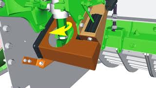
Performance, productivity and exceptional harvest experience. Go Harvest. Get the most out of your S Series combine today. Always follow safety instructions and understand all safety decals according to the operator's manual. Always use seat belts when operating the machine or riding as an observer. When parking and leaving the machine, disengage the header and separator. Move the multi function lever to neutral and apply the parking brake. Shut off the machine, remove the key and lock the cab. When performing service operations where the engine must be started, make sure everyone around is aware and are clear of the machine. Enter the cab, sound the horn and start the engine. The concave or threshing clearance leveling procedure must be performed whenever the concaves have been installed. See the concave leveling or active concave isolation section in the operator's manual. Concave leveling may also be performed as an adjustment if the concaves have not been removed. This is done to ensure correct clearance and optimize the threshing capability of the machine. The following steps must be taken prior to the leveling process. Start the engine and press the threshing clearance button and set the threshing clearance to 5. If tall, dense, pack threshing tines or rice threshing elements have replaced grain elements, set the threshing clearance to 15. Set the parking brake, shut off the engine and remove the key. Shift the rotor gearcase selector handle to the neutral position. Remove shielding and separator inspection covers on the left side of the machine. Remove one separator grate section or two heavy duty grate fingers to allow access to turn the rotor. Be sure the left side auger bed divider is in the lowest position in the trough. Remove the concave leveling cap screws from the storage position on the Z bar and install them through the rail to hold the concave and Z bar assembly hand. Tighten the lower nut against the Z bar bracket and slightly tighten the upper nut against the rail. Leave space between the lower nut and rail to allow clearance for zeroing adjustments. Remove the base of the rubber seal on both cylinders and lift upward. Remove the pin and safety stop from both cylinders. Loosen the cylinder stop jam nut. Turn the stop on both cylinder rods, lowering the stop at least 15 millimeters from the original position. Remove the quick locks and pins from both cylinder rods. Note that if concaves have just been installed, leveling as described in the operator's manual would normally start with the machine in this current stage of reassembly before beginning concave leveling. Concave inserts if installed, should be removed. Slowly spin the rotor. While tightening the rear leveling cap screw, the concave is pulled upward until a ticking sound is heard when rotor elements begin to lightly contact the concave. Once ticking occurs, back off the leveling cap screw, three complete turns. Continue spinning the rotor and tighten the front leveling cap screw until rotor elements tick the concave Back off the leveling cap screw, three complete turns. Repeat these steps a second time, this time only backing off the leveling cap screws. One and a half turns. After ticking, tighten the lower nut on the leveling cap screw against the rail to lock the concaves in position. Disconnect the harness from both concave leveling sensors to allow the system to enter manual mode. Enter the cab and start the engine. Press the threshing clearance button and touch the minus symbol or rotate the selection dial until the concave cylinders are fully retracted against the stop. Threshing clearance will not be displayed. Since the system is in manual mode, only dashed lines will be available. Set the parking brake and shut off the engine. Turn the key switch back to the on position. From the combine main display screen, select the calibrations icon. Then select Threshing clearance Leveling from the drop down list. Follow the on screen instructions to perform the calibration. The key switch must be left on while performing the following steps outside the cab. In the threshing clearance leveling calibration, the cylinder stops are adjusted so the pins can be installed through the cylinder rod and Z bar. Before adjusting the stops, check to be certain the stops are bottomed against the cylinder barrels. No gaps are permitted. Failure to do so may result in separator damage. Rotate the stops counterclockwise viewed from the top until the rod pins slide through the rods and Z bar. Install the pins and secure with quick lock pins. Tighten the jam nuts against the cylinder stops. Install the cylinder safety stops and pins. Reconnect the position sensor linkage and harnesses. With the leveling cap screws still holding the concave in place, continue with the next step of the threshing clearance leveling calibration. If the calibration was accepted, exit the leveling calibration mode and turn the key switch off. Remove the leveling cap screws from the Z bar and place them in the storage position. Start the engine and enter the calibration mode and calibrate threshing clearance. A warning message may appear stating that the system has detected a concave zero position that does not match the concave leveling position. Abort the threshing clearance calibration and repeat the threshing clearance leveling procedure, then calibrate the threshing clearance. If issues continue, contact your John Deere dealer. After successfully completing the threshing clearance calibration, open the concaves and verify the hardware is tight and cylinder safety stops are correctly installed. Reinstall the bottom of both rubber seals. Reinstall any separator grates that were removed and shift the rotor drive gear case back to the original position. Install all previously removed separator inspection covers and shields. For more detailed information, consult the operator's manual.