Tips for reading wiring schematics

HVAC trainer Mike Plezia teaches apprentices how to read electrical wiring schematics for package units. He covers key symbols, line conventions, and how to trace circuits left-to-right and top-to-bottom. Using an iced evaporator fan failure as an example, he shows how to isolate the fault and verify the system works after repair.
Chapters
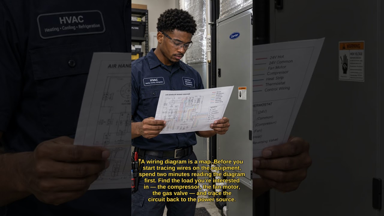
Good morning, everybody. It's Mike again with some helpful tips for you HVAC apprentices and new people learning the trade out there. Today we're going to talk a little bit more in our continuing series about reading electrical diagrams and schematics. This is an absolutely key and vital skill that you're going to need in the trade. Even if you're brand new and have never opened the service panel on a heating or air conditioning unit, to have a general understanding of the wiring and the circuitry within the system is going to be absolutely vital to understanding what's going on, to be able to diagnose and eventually repair. So just going forward, as we've said before in past videos, the wiring diagram reads From left to right, top to bottom, just like you're reading a book. So when you are looking at your wiring diagram, you'll notice upper left corner is where the power is generally going to be starting. This is where you're going to start your circuit. So unlike the basic circuit wiring diagram that I went over previously, or the little bit more complicated basic control board diagram that I showed you in a previous video on a gas furnace. This one is a little bit more complex. That is going to bring up the question of what is a schematic versus a wiring diagram? Well, the definition of a schematic is simply a chart or an outline of the scheme or plan of the way that a machine works. So really, a wiring diagram or any other diagram really is a type of schematic. When we're talking about wiring schematics, frequently we're referring to a little bit more complex machines. When we're talking about something that is simpler, we usually just talk about the diagram. But just for all intents and purposes, the, the terms are kind of interchangeable. But usually, we would refer to a schematic when we're speaking about something that's a little more complex, multiple circuits, and just a lot of stuff going on, as you can see. I usually like to refer to this as the spaghetti, because when you look at it, and when you open the machine, you'll sometimes see like a spaghetti of wires. Some of the first package units, and yeah, package units that I dealt with in the apartment business, were, uh, through the wall. And by package unit, I bet— I mean they are both heat and cool together through the wall in the case of the machines I dealt with then. But they were very old, had been touched by many, many maintenance men and many contractors through the years, and there were wires run everywhere. It was a mess. It looked like a jumble of spaghetti. So I usually like to refer to this as the spaghetti. And if you're new to this and you maybe you've never even seen a wiring diagram this complex, and this isn't that complex, then it may look like a jumble of spaghetti to you. But I assure you, every line has a purpose, every wire, every connection has a name. It's not just in there to confuse you, but it is a purpose. The key is to understanding how to zero in on what it is you're looking for. So just a few key points here within this particular schematic. You're going to see that you have your power supply coming in. So again, upper left corner is where the power is entering the system. Okay, this is a 3-phase, uh, 208, uh, 230-volt, uh, 60 Hz system. How do I know that? By the way, the system can also be configured as a 460-volt, 3-phase, 60 Uh, 60 hertz system. The reason I know that is that right here under power supply, it's telling us our voltage, our phase, and our hertz, which is— we can go over what hertz means in a future video, but basically it's the amount of waveforms per second, how many times the, the positive and negative, uh, electrons are moving, uh, back and forth. Uh, throughout the circuit, uh, so 60 times per second. If you see, I have a light here. Believe it or not, this is blinking 60 times each second. Uh, your kitchen light is turning on and off 60 times per second. Uh, your cell phone charger, when you plug it in, is actually connecting and disconnecting 60 times every second. Uh, we do not perceive this, uh, on and off, this rapid cycling, because it's, it's It's something that our eye can't catch, but every— most, especially in the United States, and as far as I know in the rest of the world, most power is running on 60 Hz waveform. Um, as power is entering the system through this triple throw, uh, switch, uh, we see that— and by the way, this is a series of switches that are all connected, so they open and close together in unison. All power goes through these fuses. So you see they kind of look like the glass cylinder fuses that you would use, like, you know, in your car or something, in your car stereo system. This is— that's what this symbol means, is that's a fuse. So if you notice, most of these lines are solid, right? But you see here you have dotted lines, dotted line, dotted line, you know, some dotted lines here. If you look down in your legend, which I'll scoot the book— textbook up a little bit, you'll see that dotted lines are field wired and solid lines are factory wired. You'll also notice that in this instance, a dark, a dark bold line is going to be high voltage, whereas the little bit lighter Thinner dark lines, whether solid or dotted, are going to be your low voltage, which will be your control voltage. Uh, um, yeah, your control voltage. So another thing to notice too on wiring diagrams, and you've seen me do this in past videos, is drawing this little arch over a line. If you see that little arch, that means that where 2 lines cross, that is not connected. It's just, you know, they're crossing each other. But they're not connected. If you see where the lines have a little ball, and looking up here, you can see there's a little ball, a little ball, a little ball. Those are actually, uh, actual physical connections in the wire. So this is a 3-compressor— excuse me, a 2-compressor, uh, 3-phase motor. You've got your linkage for your, your thermal connection as well as your normally open contacts. So, um, you know, like let's say you're installing a brand new system, you're probably going to be wiring in, uh, you're gonna have your disconnect up here, fused link, and then you're going to be wiring in to L1— oh, LL1, LL2, and LL3 is where you're going to be physically connecting wires in the field into this system. You'll see that you have The low voltage, or rather the high voltage, again coming through a thermal disconnect. That's what this little S is. Um, so a fused link, fusible link, or thermal disconnect, which is then going to come down to your transformer and step down your control current where it's going to, um, basically run your contactors and, and either energize or de-energize your contactors, allowing the switches to open or close. Uh, so over here you're going to see that primarily power is going to go to your 2 compressors. So again, this is 3-phase. We don't have a run, start, common. All 3 coils are energized in your 3-phase motors. You have 2 compressors, but you actually have, um, you have 2 also corresponding condenser fan motors, and then this is your evaporator fan motor. So, this is where I actually stand corrected. This is a package unit. It would not have an evaporator, uh, the evaporator fan motor would be on the indoor unit, if it were not a package unit, but the evaporator fan motor is here. So, you're gonna also have refrigerant lines that aren't going to be On this diagram because it is— those are not electrical, those are refrigerant. So your evaporator fan motor also running off of 3-phase, being run off its own contactor. So, um, that's, that's going to be running the fan on the evaporator coil. Uh, you have 2 evap— 2 condenser fan motors down here. It says the inherent protection, so you're going to have a thermal limit switch inside. Uh, which, um, is probably represented by these thermal switches here. There's an open— oh no, yeah, open on rise and an open on fall limit switch. Those are your low— your low ambient sensors are going to be here. So if your outdoor air temperature is too low to allow the head pressure to rise quickly enough, the system will shut down. It will not allow itself to run. You also have your capacitors for your condenser fan motors here, and then you have your first low-pressure switch, your first high-pressure switch, along with your normally closed contacts and your, your, again, high limit. So yes, this is a package unit. You have your heat here. This is your heating coil. I'm sorry, guys, apparently I didn't look at this thing closely enough. Yeah. Before I started this video. But you know what, we're not perfect. Um, but we have our heating coil here. So we have an electric heat strip, and then again you have your high and low pressure switches, and then a, a control transformer down here at the bottom. So basically what we want to keep in mind is that this is not just, you know, this condenser motor wasn't put here just because that's where it fit on the diagram. This is actually also the order of operations, okay? So, first compressor comes on before second compressor, okay? Evap fan motor should be on if any of the compressors are on, okay? If compressor 1 is on and evap fan motor is not on, then obviously there's a problem. Um, so when we, when we look at our schematic, we can find where our problem lies. So let's say that we're getting— we have an iced-up evaporator, um, and our— we hear our compressor coming on, we check our pressures. Okay, so, you know, maybe pressure's a little low or whatever. It's gonna seem low because the, the The condenser coil— or excuse me, evaporator coil's iced up, but then we notice that the fan motor is not coming on. So, you know, we do an amp draw test and the evaporator fan motor is not coming on. Well, there's a problem right there. So the compressor is going to eventually kick out on high pressure, and then, you know, the whole system is probably actually going to trip out. The— that draws your attention to the evaporator fan motor. You don't need to pay attention to this heating coil. You don't need to look at the condenser motors because they're not there. You're not there yet. If the problem is that the evaporator fan motor isn't turning on, then, then you don't need to go any further. So again, that's just a point, just to make the point that we need to train our eyes when we're reading schematics to focus in on the problem and ignore everything else. You don't need to worry about the rest of the spaghetti. You just worry about as far in the wiring diagram until you find a problem. Now, as good technicians, we are going to then test the rest of the system once this evaporator fan motor is repaired. We may just need to replace a capacitor, or if it's the motor itself is replaced and we're back up and running, we need to now start at the beginning and test through the rest of the system to make sure the rest of the components are working As they should. Just because you fixed one part, and I've been guilty of this myself in the past, this is something that all new techs face. Just because you fixed one problem doesn't mean that there isn't something further down the line. You've got to check the whole system and make sure that all components and features are running, everything's turning on as it should and shutting off as it should before you walk away from So this was just a simple look at the schematic diagram. Definitely looking forward to doing more of these videos for you guys. Stay tuned as more content is rolled out to you. This is Mike once again, happy to help you guys out. If you have suggestions for other videos or things you need help with, feel free to comment or send me a message. Definitely shoot me a like and, you know, You know, if you have questions again or suggestions, uh, and like on Facebook as well as on YouTube and TikTok. Uh, have a great day and we'll talk soon. Bye-bye for now. Bye.