The presentation by project engineer Ravindra Mahara (with Speaker B) details a case‑study of redesigning the fines removal conveyor system for a blast furnace handling 7,200–9,000 t of hot metal per day. The existing system, comprising oscillatory and transport conveyors feeding a narrow‑bottom hopper, suffered frequent blockages and material clogging. The proposed solution replaces the legacy arrangement with four new conveyors – two flat‑belt conveyors for raw‑material feed and screening, and two trough‑belt conveyors to collect and transport the separated fines to a skip‑car trolley. Design work covered layout planning, 3D modelling, detailed engineering, and structural analysis using Eurocode as the design basis. A key innovation was the optimisation of load‑cell placement: the original concept of eight short posts and eight load cells per conveyor was reduced to six of each after detailed analysis, cutting hardware count and simplifying the structure. Material stacking properties were studied to generate realistic load profiles, and the entire structural analysis was performed in‑house with general‑purpose engineering software rather than high‑end FEM tools. The design also addressed beam stiffness to avoid tension loads on the load cells. The project delivered a seamless, blockage‑free fines removal process, meeting timeline, quality, safety, and cost objectives, and received client approval.
Chapters
Hello everyone, we would like to present you a case study on a project for revamping of conveyor technological structure of impro fines removal system in blast furnace of steel plant. I, Ravindra Mahara, engineer of the project, would like to take you through the process of design for replacement of this existing fines removal system with a new seamless conveying system. This project involves analysis, verifying designs adequacy and strengthening of the structures. The design and analysis of this structure is carried out with Eurocode as a design basis.
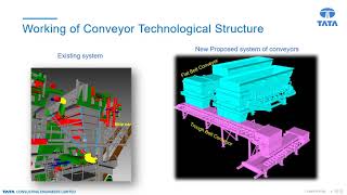
Coming to the project description, the design capacity of blast furnace is 7200 tons hot metal a day and can go up to 9000 tons of hot metal a day under favorable condition. The below picture shows the process flowchart of blast furnace in which this Highlighted zone represents the TC's work area where existing fines removal system is located. And here, for the process of iron making, blast furnace requires feeding of raw material through conveyors which is stored in storage bunker in stockhouse of the blast furnace. Here this raw material is in the form of sinter pallets, coke, limestone, etc., which were originally conveyed with the help of oscillatory and transport conveyors here. And thus in this process, fines used to get collected in the fines hopper. TC's scope for the project, and it involves design and analysis of structure, selection of loads and as per calculation, preparation of layout and detail engineering stage, preparation of 3D model with drawing extractions, connection design, and engineering support to the contractor. And to this, timeline, quality, and safety features during execution were also taken into consideration at the time of design. The existing arrangement of conveyors and hopper system for fines removal, where the raw material goes to the transport conveyor from oscillatory conveyor. As you can see here in the P&ID of the system, this material later moves to the vibrating screen, and there this fines get separated, and the larger particle goes to the baking bunker as a feed to the blast furnace. The separated fines falls into the fines hopper, from which it is then transported by oscillatory conveyor to skip car at the bottom and then taken to the fines bunker for further processing. But this existing system was experiencing the problem of blockage, as a splitting and clogging of material. Here you can see the profile of hopper which is narrow at the bottom and due to continuous loading and unloading of fines into skip car, it is experiencing accumulation of fines and thus creating blockage in it. And as a solution to which, to avoid this issue, This existing system is being engineered with 4 new series of conveyors, 2 flat belt and 2 trough belt conveyors. And the arrangement is like this, where you can see the raw material will be fed at the top of flat belt conveyors, which will have the screening at the end where the fines will be separated. These fines are then collected at the trough conveyors below the flat belt conveyors. Here, 2 interconnected trough conveyors are there and at the end of the second conveyor, the fines will be unloaded into the skip cart trolley, and from there it will take fines to the fines bunker for further processing and thus completing the removal process of it.
In best practice and innovation, challenges faced were design and analysis of the conveyor structure using general-purpose structural engineering software, seamless process of the fines removal and idealizing the concept of load cells. As mentioned earlier, for the load cells, it is used in the conveyor structure to measure the material weight in it. The highlighted marks are the location of the load cells, which is above the short post of the conveyor. However, in below pic, you can see the idealized structure in design software, where the highlighted mark shows the position of the load cell in it. And before idealizing this concept in basic engineering stage, It was proposed to go with 8 short post and 8 load cell in one conveyor. But in detail engineering stage, after detailed analysis of the structure, the number of load cells and short post were reduced to 6 numbers per conveyor. Thus total reducing 4 number of load cells as well as short post. And for analysis part of the structure, to get the exact material profile, TC did a separate study on material stacking properties. And then material load is applied accordingly. Also, such type of analysis of mechanical equipment generally requires a high-end spatial FEM software, but the same structure has been designed and analyzed in-house in design software keeping all idealization and calibration into consideration. Now here, one pair of short post leg of conveyor structure is resting on steel platform beam as shown here. While two pair of legs on concrete surface, and due to which the steel beam is subjected to bending, and which will create tension in load cell. Thus, the stiffness of this beam on which the short post leg is resting is kept in such a way that no tension load is registered in the load cell. Thus, structure was designed keeping this proper simulation in software as well.
Finally, coming to the value additions done to the projects. The design work carried out by TC did ensure installation of the series of conveyors along with minimizing the number of load cells and short posts, thus contributing significantly to the project budgets. The successful analysis of the structure in design software with proper backup calculation help eliminates the need for using high-end FEM-based software. This avoids the licensing cost of specialized software resulting in reduction of project cost to TC. The design hence approved by client as well. Summarizing to which, this, this successful execution of this complex project through TC's Way of Working demonstrated the commitment to quality, timeliness, and cost-effectiveness. Adoption of standard systems and procedures helped fulfill the project objectives and TC values. Thank you.