Control a Remote IoT Device by Node-RED App and IBM Cloud
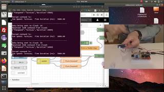
Richard Li shows how to build a two-way IoT system where a Particle Photon sensor publishes readings to IBM Cloud, a Node-RED app triggers Twitter alerts when values cross thresholds, and sends commands back to control LEDs and a servo. The demo uses MQTT messaging and includes both string and JSON command formats.
Questions this video answers
Richard Li
2020-04-25
About 20 steps (first 16 same as Lab 7).
ArduinoJson
Chapters
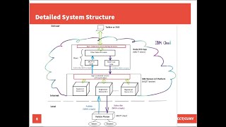
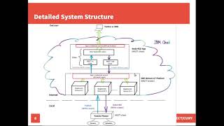
Hi there. How's it going? In this lab, I'm going to show you how to control an IoT device by using Node Radar app and IBM Cloud. Here's the outline of this video. First, I will briefly explain the objective of this lab. Second, I will quickly go over the system structure and the major components that we're going to work on. Then I'm gonna give you a lab demo. After that, I will show you the entire procedure. Here's the lab objective. In this lab, we're gonna build an IoT system in which a particle photon connects a sensor, reads and publishes the sensor's reading to a cloud. We're gonna use IBM Cloud in this lab. A Loaderator app running on IBM Cloud subscribes, receives and processes the sensor readings. It will automatically trigger alert if the sensor data meets certain conditions. In addition, we also automatically generate a control command and send back to Particle Photon. The Particle Photon subscribes, receives the control command and take certain actions accordingly. For example, to spin a DC brushed motor faster or slower, drive a DC server or stepper motor to different positions. Here is a very simplified diagram showing the system overall structure. Basically, it has three layers. Local, Cloud and the end user. In the local, we're going to use the Particle Photon to connect sensors and actuators. On the cloud, we're going to use IBM Watson IoT Platform and Notorator App, which are the two services we're going to use on IBM Cloud. For the end user, we're going to send them the alert tweets. In this slide I have a detailed diagram to show the detailed system structure. In the local, the Particle Photon connects a sensor and actuator like DC Server that I'm going to use for the live demo. Of course, it can be some other types of actuators used for your own projects. The Particle Photon reads the sensor measurements and publishes the sensor's readings to the cloud. On the cloud, we use IBM Watson IoT platform to register and manage the IoT device. The Watson IoT platform also plays the role of MQTT broker. On top of that, we're going to create a loaded app running on IBM Cloud to subscribe and receive the sensor's readings through the MQTT broker. If the sensor reading is greater or smaller than certain threshold, it will automatically trigger alert tweets and send to the end user. In addition, the Loaderator app will automatically generate a control command and publish it back to Photon through the MQTT broker. The Particle Photon subscribes and receives the control command and take certain actions according to the received commands. In this lab, we can let the loaderat app automatically generate the control command. Of course, you can configure your own load radar flow to let the end user to initiate the control command and send it back to the photon. So, through the MQTT program, Here's the major components that we're going to work on for this lab. For the local particle Photon, we need a program to publish sensor data, subscribe, receive and respond to the control commands. On the cloud, we need to Register manage the IoT device. As an optional work, you can use the visualization boards and cards on IBM Watson IT platform to visualize the sensor data. Third, we need to create a load radar app to subscribe the sensor's readings, compare the data with predefined thresholds, trigger Twitter alerts, and generate and send the control commands back to Photon. By the way, here is the major component for the previous Lab 7. You can find Lab 7's video through the link below. Over there we just need to program the IoT device particle photon to publish sensor data. On the cloud, we just need to Register manage the IoT device and create a loader app to subscribe the center data, compare the data with predefined threshold and trigger the Twitter alerts. So compared to lab 7 for this current lab, we just need add two major components here. One is to program the particle Photon to subscribe, receive and respond control commands. For the Loaderator app we need to add we need to expand the flow to generate and send the control commands back to the particle photo. Now let me give you the live demo. Before I start, let me turn on the camera on my laptop. Then you can see what I have here in front of me. I have the finished circuit here. Here's the particle photon, the red colored board right under the Particle Photon. Here is a battery extension board made by SparkFun. By using this battery extension board, you can use external power supply or battery like this Liam battery pack here to power up Photon, Here's a potentiometer which is used to mimic actual sensor like this temperature, humidity DHT 22 sensor. The issue with using an actual sensor is that it may not give you a reading you want in order to trigger the alert and the associated control commands. Instead, by using a potentiometer, you can just simply adjust the potentiometer's position here and get a reading to trigger the alert and control commands. Anytime you want, you flash the code into the board. The code should start running any second. Here we Go. Yes, we see this blue colored LED blinks. That means data is published to the cloud. And this, the yellow colored LED blinks that indicates control command is successfully received by a particle photon. I bet right now the control command is turned on so this green color LED blinks For this first demo here the control command is a stream tab and let me go back to the cloud and take a look what a control command is being sent and let's verify that and then we move on to the second demo. Right now Xero is being sent to the cloud and then control command is published from the cloud and received by the photon. And then let me open up the Loaderator app. Here we go. All right. That's the first demo in which the Node Radar app generates a string type of command to control the particle photon. The issue with a string type of command is has a very limited capability to pass on multiple control parameters. For example, if you want control the servo motor to stay at a certain position for certain period of time, the string type command cannot do that. So a better option is to use a JSON format control command, which is the second demo I'm going to show you. Let me disconnect the USB cable and power off the photon and set up everything. I'm gonna add up the server motor into the circuit and let me fire up another node Radar app I have already created for the second demo. This is a separate node radar app I have already created specifically to generate JSON format control command. Okay, right here. Okay, it's turned on. And then let me flash it as a code I have already written for the particle photon to receive and respond to the JSON commands. Okay, the code is successfully flashed and let me open on the camera for you. And then you see what I have here. I have the server motor connected already. Let me restart the code from the very beginning again. Okay, that's the initialization. Sweep the servo motor a little bit to initialize and right now it's in the nominal position, the 90 degree. Here we go. We have this blue colored LED link that indicates data being published by the particle photon to the cloud. And a yellow colored LED blink indicate turn. No control command is being received. And then the server motor moves to a lower position which is zero degree. Here you go. And stay there for a few seconds and then resume back to the nominal position, the 90° as terminal control command. A JSON format control command is generated by the node raid, which includes a time duration sophistication and then the server motor can follow the control command and then keep the position, the lower position for certain seconds. And then right now I guess the sensor data, the dummy data published by the particle is not in the any range to trigger the control command. So here we go, we have the red colored led. That means a high control turn high control command is being generated and received by the particle photon. And then server motor moves to the high position and stay there for a few seconds. Then let me open up the serial communication between the host computer and my photon can see what is the exact control command Here go. We have 80 dummy data being published to the cloud and turn high control command being generated by the notorator app and the particle photon received. And then move the solar motor to a high position and stay there for 3000 milliseconds and we have 90 being sent to cloud and turn high been triggered and being received and then remain there for 3 seconds and 100 and then we have turn high and then right now zero and then the server motor should move to the low position which is 0 degree and stay there for 5 seconds. After 5 seconds goes back to the nominal position which is a 90 degree. And here we go, we have another turn, no command being received and the servo motor moves to no degree, 0 degree null position and then stay there for 5 seconds and then goes back to normal position. Here we go, we have another terminal command come in. And the LED blinks corresponding probably should receive the control command. The motor server motor moves low position and stay there for five seconds and then return back to the nominal position. Here we go. Perfect match works perfectly. Then right now the dummy data is faulty and no any control command is being triggered. All right, that's the second demo. I think it works perfectly as what we planned. Okay, let's get back to the procedure. The entire Procedure has about 20 steps, but please be noted, the first 16 steps are the same as previous Lab 7, so you can refer to Lab 7 video for details. The video is posted on YouTube and the link is right here. You can also find this link in the description right below. To save time, I'm gonna just read the steps here to you. Step 1 Login to IBM Cloud and launch Watson IoT Platform. Step 2 Create a device type on IBM Watson IoT Platform. Step 3 Register a device ID on IBM Watson IoT Platform. Step 4 Change connection security setting on Watson IT Platform. Step 5 Build a circuit to connect a potentiometer with particle photon. Double check the circuit, connect photon to a host computer for proof of concept. You can just use a potentiometer instead of an actual sensor for manually activated the Twitter alert message anytime you want. Step 6 Log into Particle Online ID Verify Photon's Internet connection, use the registered device credential information and program the Photon to publish sensors reading to IBM Cloud. You can refer to my example code for Lab 6 which has been posted on CityTech Robotics Research Labs website. Here's a link. Another tip here is Take notes about the event ID and data property used in your code because there will be needed later by IBM Cloud. Step 7 Go back to Watson IT Platform to create a board and a card to visualize the sensor data. Note when you set up Connect Dataset for your visualization card, make sure that event and property fields exactly match what you are using in your photons code. Step 8 Open your IBM Cloud Dashboard Open Catalog software Launch Nodovator App Service Create a Node Raider app. Note during this step you will also create a cloudant service, a Secret Store service or developer toolchain instance. You can save your Node RAID apps API key on IBM Cloud by using Secret Store service. Step 9 Connect the newly created Node Radar app with the Watson IoT Platform Services instance where you used to register your IoT device. Make sure verify the status of your IoT Platform Services instance is active. Note both your IoT device which is the Particle Photon and the Node Radar app are MQTT clients. The MQTT broker is IBM Watson IoT platform. Step 10 start the node Radar App Editor on IBM Cloud Note right after the username and password just been created, attempt the first time login to the editor mainfield. So you can just simply wait for a little bit while and try it again. If the username and password to login to the loaderata app editor are lost, you can manually reconfigure them by setting loader username and load radar password these two environment variables on the app's Runtime sliders page. Step 11 make yourself familiar with the Node Red editor's GUI and features. Create a load RAID flow. You can refer to my example Node Rate flow post on Cititech Robotics Research Lab website. Step 12 Replace the IBM IoT node in my example flow by mqtt endnote Set up correctly Here I have detailed instruction showing you how to set up the mqtt end node. You have to set up the server client ID username password topic for the mqtt in node. That node is extremely important. You have to be very careful when you set this one up for details. You can Refer to previous Lab7 videos for details. Next Step Step 13 Login to Twitter Go to developer.twitter.com to apply for a Twitter Developer account if you don't have one yet. Note Access to standard API is good enough for most cases. Yes, you need to answer all those required questions when apply for a developer account with Twitter most time your application will be approved quickly. If you have an academic email address, select Academic for the primary reason for using Twitter Developer Tools. Then your application may get approved instantly. STEP 14 Log into your Twitter Developer Account Create a new Twitter app on the app page. Use your Node Rate apps URL for website URL and callback URLs. Be careful to keep a record of your Twitter apps API and API secret key, API token and access token secret because all this credential information will be needed by the Loaderator app. Step 15 Go back to Node Radar Editor Install Twitter Node Insert a Twitter out node into the flow correctly set up Use your Twitter app's credential information to set up Twitter out node. That means you have to put in API key API secret key it's access token and access token secret into that node to set up and then that Twitter out node can smoothly communicate with your Twitter app. Step 16 Run particle photons code View data Visualization inboard card on IBM Watson IoT Platform view Twitter alert message being posted on your Twitter page. You can use a serial communication tool such as Putty or Table term in Windows screen in Linux and macOS to view and verify the data actually being sent out from Photon by here. All these 16 steps are the same as previous Lab 7. Again you can go view Lab 7 video on YouTube to see the details. The videos link is posted right below and start from here are the new steps we have to add on based on the previous lab. Step 17 update load raid flow to generate and send commands go to load RAID flow editor from the load pan it drag and drop function node into the existing flow. Edit the nodes to generate control commands. You can refer to my example flow post on CityTech Robotics Research Lab website. I suggest you try string typed command first and then JSON formatting later. You also need drag and drop or mqtt out node into the flow and then set up correctly. The way to set that node up is very similar to mqttin node. How to set the mqtt endnote topic property you can set up as this and here let me show you how we finish this step. First of all go to CDTech Robotics Research Lab. And open up the example flow which I post here for lab 8 lab 8 control remote device through notary and IBM cloud I write this example node red flow for sending commands to remote devices. Click open up, copy paste and put it into your Node Radar app. The UTT end node is for the entire Node Radar app to subscribe and receive sensors reading through MQTT broker. The mqtt out node is for the Node Radar app to publish the control commands to the mqtt broker. Then later the particle Photon can subscribe and receive the control commands through the broker. Here let me show you how to set up these two nodes. Let me start with the mqtt out node. It. That's the flow here and we can move on to the next step. Before we move on to the next step, here's one tip for the mqtt out node here. Do not use any wildcard for the topic property but instead you can use wildcard for the mqtt in nodes topic property like the one we are using here. Here for the format use whitecard which means there's something you should keep in mind. Alright, let's get back to slides and check out the next step. Step 18 Update Photon's Code to subscribe, receive and respond to stream tab commands. You can refer to my example code post on CDTech Robot Rotix Labs website. I have one tip here. Make sure the command id in the code match with the one used in MQTT Outlook of your Node Radar app which we have already done. Another tip here is you can add LEDs into your circuit, write code to bring them as indicator for population data and receiving commands. The example code is on the CityTech Robotics Labs website under the Lab 8. I have this example code for Photon subscribing and responding to three commands from IBM Cloud Click open up you can read about as a example code. Actually I have already copy paste this code into here. That's what we used before already. Alright, Let's move on to the next step. If you want the Notorator app to generate a JSON format commands of course first thing we need to do is to modify the notorator app flow to generate a JSON format commands. Go back to the notorator app flow you created before you and we don't need to change that much here. The only thing we really need to change is to modify this function node instead of here generate a string type command and then we have to replace this one by JSON format command. I have the sample code here so just come out this one and now we have this non over jar scripted code to generate a JSON format commands, we have test command the name of the field and then the actual value here is turn null. Very simple. By using this line of code, your MQTT payload will have a JSON format control command and then just return this message. Okay? Very straightforward. For the other function node we can do the same thing. Command out to string type of command and then use this one to generate a JSON format command and then down we finished the load rate apps updates. You can deploy it. Then let's take a look. What do we need to do next? We finish the node radar apps. Now we need apparently we need to modify the photon. You can refer to my another example code posted online IoT course page located on CityTech Robotics website located the example code which is for Labor 8. Here's the example code you can refer to, but please pay attention to the date of the last update. I was using a library called Arduino JSON to parse the receive control command. This library might be updated lately, so you need to check out whether and how you need to update this code. Rewrite my example code to use updated Arduino JSON function to receive and parse JSON formatted commands. Search and refer to the official documentation for tag details. Here is the link of the official Arduino JSON website. Let me show you how to do that. Specifically, in this example code, I was using JSON buffer to store the received JSON format control commands. If you check out the Arduino JSON official website, here is the site you will find how to update the JSON buffer. As a first line you need to update here. Another part of the code you need to update is this parse object function. That was the function used by the library to parse the received JSON control commands. Go read the official documentation of Arduino JSON. You will find out how to update that function. All right. It's quite straightforward. I have the updated code here. I already replaced the JSON password by JSON document. I will also already replace the parse object by deserialized JSON. That's how you parse the received control commands. Pretty much that's it. And over here you need to update your code to extract the actual value from the JSON control commands. We're done with the code. I have a tip here. Make sure the control command ID in your code match with the one used in MQTT out node of your notivator apps flow, which we have already done. Let's move on to the next. Step. 20 Verify Photon's code, correct any error if there is flash and run the code on Photon. Adjust Potentiometer's position. You should see the expected moment of your motor and LED indicators. If you have one, you can use a serial communication tool, putty table, term or screen to view the actual data being published from Photon. You can view and verify data visualization on IBM Watson IoT platform. View and verify debug message in the debug view of your Node Red apps editor. You can also view the alert tweets post on your Twitter. Let's give it a run. Everything right now should be up running correctly. Okay, here we go. The code starts running in the particle Photon and it connects to IBM Watson IoT platform and stores and the data to the cloud. Zero is just being sent and immediately turned. Now control command is generated on the cloud and sent back to the particle photon. Particle photon receive it and remains at the null position for five seconds. And another number 10 being sent to the cloud and then cut out. Generate a terminal control command, send back to the particle folder. Particle phone down goes to the lower position which is 0 degree and it remains there for another 5 sec. Looks good. Let's go to the cloud. Here's the visualization card on IBM Watson IoT platform. And then we can see 4050 just received by the Watson IoT platform. And let's go to the loaded app. Here we have 40, 50, 60 being received just a moment ago and start from all the way 0 and then 10 and then 20. Okay, and let's get back to the photon. Here we go. We have 70 just published from Photon to the cloud and then cloud immediately generate a turn high control command and then server motor goes to high position which is 180° and remains there for 3 seconds. Works perfectly. Put everything together. You can see we have 100 just published to the cloud and then 0 come in the node red will generate turn null command and yes the particle photon received the turn null and goes to the lower position 0 degree and stays there for 5 seconds. Perfect. Everything works well and pretty much that's it. And over here I have a troubleshooting checklist. You can take a look over there and you can read the details of this troubleshooting checklist to help you identify any possible errors. All right, pretty much that's it. Thank you for watching and see you next time.
More from Richard
Create Node-RED App on IBM Cloud to Send Alert Tweet Based on Data from an IoT Device (Part 2/2)
Create Node-RED App on IBM Cloud to Send Alert Tweet Based on Data from an IoT Device (Part 1/2)

Video Survelliance Autonomous Robot with Android - NYCCT Course Project with Dr. Li