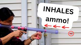
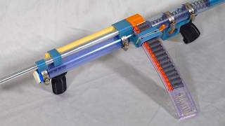
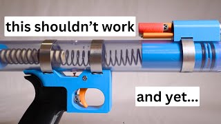
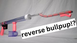
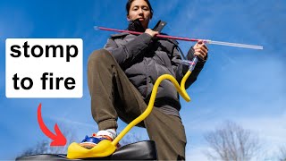
In this tutorial, the creator designs and constructs a Kirby‑themed Nerf‑style blaster that mimics Kirby’s suction and spit mechanic. The process begins with a 3D‑modeled design where opaque components are printed on a desktop printer while transparent parts are fabricated from clear (later blue‑tinted) PVC. The presenter details custom jig creation for precise drilling, the use of dowels to prevent drill wander, and the step‑by‑step assembly of printed parts—including trigger guard, pivot pin, threaded insert, O‑rings, rubber padding, and set screws. PVC sections are drilled, slotted, and combined with the printed core, adding a tactical rail, pump grip, spring, spring‑stop, and a ball‑bearing lock that holds the spring in compression. The airflow mechanism is explained: pulling the pump expands a sealed volume, drawing a dart in through the barrel, while a relief hole and one‑way valve manage residual air and produce a hissing sound. The video concludes with a functional demonstration, a subscription call‑to‑action, and a channel‑membership pitch.
Chapters
Kirby is a legendary video game character that sucks things in and spits them back out again. This Nerf blaster works the same way. Let me show you how I made it! I started by making this 3D model of the blaster. These opaque bits were meant to be 3D printed, so I loaded them up onto an SD card and fed them to my printer. While it was busy squirting plastic into the right shapes, I turned my attention to these transparent bits of the design, which I made out of clear PVC. But for most of the process it was blue PVC since I taped it all up to prevent me from scratching it. First up was the nose of the blaster, which I made by drilling a hole through the center of a PVC cap. So if the drill bit that I bought is the right size, This should just slide in here. Okay, plan B. If you're my third grade teacher, Mr. Smith, avert your eyes because I'm breaking just about every scissor safety rule you taught me. Nice. Next, I had to cut a slot into this piece of PVC in which the pump grip will slide. For this, I went to the room where my mill— picture— was, because it's also where I kept my custom tools for making this slot on my drill press. Using this angled bar, I marked a line down the length of the pipe. Then I used this custom jig to draw a bunch of crosshatches, which marked all the spots where I needed to drill a hole. To make sure that my drill bit was as accurate as possible, I made a divot at each mark, first with a pushpin and then with a hammer. This way the drill bit would stay centered and not wander. With all of that prep out of the way, it was time to drill some holes. Actually, I only drilled every other hole. Why? It's because this is the maximum number of holes I could drill without any of them overlapping. Drill bits tend to misbehave when you try to drill a hole which overlaps with an existing one. So before I drill the rest of the holes, I plugged the ones I already drilled with wooden dowels, and this made the drill bit behave nicely. After drilling and pulling out the sacrificial dowels, this was the final result. It was the next day and the opaque parts were finished, so I removed them from the print bed. To assemble the printed parts, I needed to grab an average-sized drill bit. Honestly, it's kind of above average, if you ask me. Comment below how big your drill bit is, and if you don't have one, comment what your ideal drill bit size would be. With this bit, I drill the hole into the trigger guard and a matching hole in the trigger. Then I got some help from Clippy the paperclip, who donated a piece of himself to serve as pivot pin. I installed a threaded insert into the trigger guard with a soldering iron. With the insert in place, I installed the grip with a matching screw. These two parts have a male end and a female end, which are shaped so that these two holes stay aligned. They smash into each other pretty hard when the blaster fires, so I needed to add some rubber for protection. I only glued the rubber on one side so it can flap open and expose this air relief hole underneath. Now it was time to install some O-rings. The male piece got one O-ring, and the female piece got two outer O-rings and one inner O-ring. Then I installed the barrel using a set screw. Back to the PVC now. I installed the nose of the blaster, then I slid slid in a smaller diameter pipe which will connect to the pump grip. I marked the inner pipe at the back of the slot and then I trimmed it to just under that length. Then I attached the female piece and barrel inside the inner pipe with some set screws. I put this whole assembly back inside the main pipe And you can see how this relief hole was exposed at the very front of travel, which was intended. Then I marked screw holes for the tactical rail which will hold the pump grip. Next, it was time to drill the last hole in the main pipe. I installed the male piece behind the female piece, and with the pump in the rearmost position, you can see this hole in the male piece peeking through this window in the masking tape. That's where I drilled the hole. Now that the drilling was done, I finally unmasked everything, and I also added the pump grip. After that, I added the spring and the spring stop, and I used a stick to position the spring stop at the right location before marking that location with some tape. With a bit of movie magic, I poofed some screw holes into existence. And after adding some screws, the spring was nicely contained. But there was nothing to keep it in the compressed position just yet. For that, I added a little spring and ball bearing into the hole in the mailpiece. Then I clamped on the grip and the trigger. Now when the spring is fully compressed, the ball bearing springs out and sits on top of the trigger, keeping the spring in place. When the trigger is pulled, the ball gets pushed back into the main pipe and the spring flies forward. Now let's see how the blaster inhales darts. When the pump is brought forward, the volume between the male and female pieces expands. And since they're sealed all around, the only way for air to enter that volume is through the barrel. This causes the dart to be sucked in until it's stopped by the female piece. Some darts have a tighter fit than others, so to make sure even the tightest darts get all the way in, I made the inhaling volume larger than the volume of the barrel. This means that most of the time the dart is fully seated before the pump returns to its starting position. Because of this, I needed a way to let a little bit more air into the blaster even when no more air can enter from the barrel. And that is when this relief hole comes into play. Once the pump reaches its starting position, this hole is exposed and it allows air to enter, which makes a short hissing noise. When firing, air cannot escape from this hole because the red rubber padding acts as a one-way valve. The only way for air to exit is is by shooting the dart out. If you're enjoying the video, make sure to subscribe so you don't miss out on future content. And if you want to support me directly, you can become a channel member, and in return you'll get early video access and you'll see your name in member shoutouts just like this one. Thank you so much for watching, and now let's finish out the video.