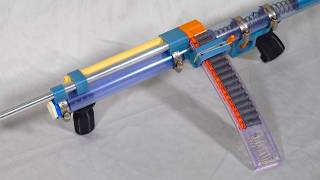
Matthew Yuan built a Nerf blaster that shoots backwards by redirecting airflow 180 degrees, making it more compact without losing power. The design uses a wooden plunger rod, 3D-printed parts, and a string-controlled transfer tab to move the barrel and magazine together as the pump cycles.
Chapters
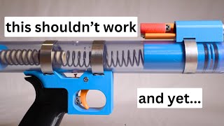
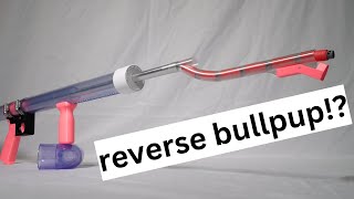
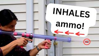
This is my homemade backwards Nerf blaster. I know that sounds silly, but hear me out for a second. 3, 2, 1. In my previous video, I made this blaster, which was cool but kind of long and unwieldy. That was because it used a rather long plunger tube to push air and a dart down a rather long barrel. But what if I could redesign the blaster so that the air turns a 180 like this? Then I would have the same power potential in a shorter overall package. What I have here is a stepping stone towards that final idea. 3, 2, 1. After a bit more work, I turned it into this. Let me show you how I built it and how it works. Here are all the parts of the blaster laid out. Assembly begins with the wooden plunger rod. On the back of the plunger rod lies the 3D-printed plunger head, which is made with a groove that accepts an O-ring. A spring slides onto the plunger rod, followed by a washer and a piece of small diameter clear PVC. PVC has a square inner collar which aligns with the square plunger rod. Finishing off this component is the plunger tail. It is press-fit onto the plunger rod and retained by a cross pin. Next up are the trigger components. The head of a Nerf dart slides into a hole in the 3D-printed trigger housing. The trigger is placed in front of that and is retained by a pivot screw. Pulling the trigger makes this top screw move upwards, and the dart head acts as a return spring. The plunger rod components are now slid into the main body of the blaster, which is a length of large diameter clear PVC. A rail piece screws into the inner PVC through a slot in the main body. Then a pump grip clamps onto the rail. When the pump grip is in the forward position, a hole in the plunger head aligns with the hole in the main body. A spring and steel ball are inserted through this hole, then the trigger components are screwed on to retain the ball. Two 3D-printed bands are fit onto the main body, so that these screws have sufficient thread engagement without protruding into the main body, which would interfere with blaster operation. Now, moving the pump grip compresses the spring while the plunger head remains stationary, since the ball blocks its movement. Pulling the trigger pushes the ball into the plunger head, allowing it to fly backwards. The grip is now attached with a single beefy screw. In the back of the main body, a plug and a hole redirect air through a coupler block, which is screwed into place on top. The barrel fits into this block. So this prototype might look complete, but there's a problem. The spring doesn't stay compressed. To fix this, a springy tooth is screwed into a hole in the pump area. This tooth catches on the inner PVC when the pump is brought to the rearmost position, locking it in place. After firing, the plunger tail pushes the tooth out of the way, allowing the pump and plunger to be brought forward again. Now our stepping stone is complete. What remains is to add a magazine and a forward-facing barrel. First up is the magwell. A catch piece goes into a slot in the back of the magwell, then a retainer screws on behind it. A rubber band wraps around to provide catch tension. The magazine has a notch which interfaces with the catch, holding it in place. Retracting the catch releases the magazine. Next is the barrel. Rather than being fixed in place, the barrel slides along its axis within a pair of support pieces. Its motion is controlled by a transfer tab screwed into the inner pump tube. A knotted string runs through the tab and is looped around anchor points on both ends of the barrel. Now when the pump moves, the transfer tab hits the knots, which then pull on the barrel. The knots are somewhat spaced because the barrel doesn't need to travel as far as the pump. The rear string anchor is also where the magwell is attached. This way, darts in the magazine are presented just behind the open rear end of the barrel. The final step is to replace the prototype coupler block with a skinny tube. The barrel and magazine move backwards to simultaneously chamber a dart and form a pathway for air from the plunger to the barrel. What do we think? Did I hit the center?